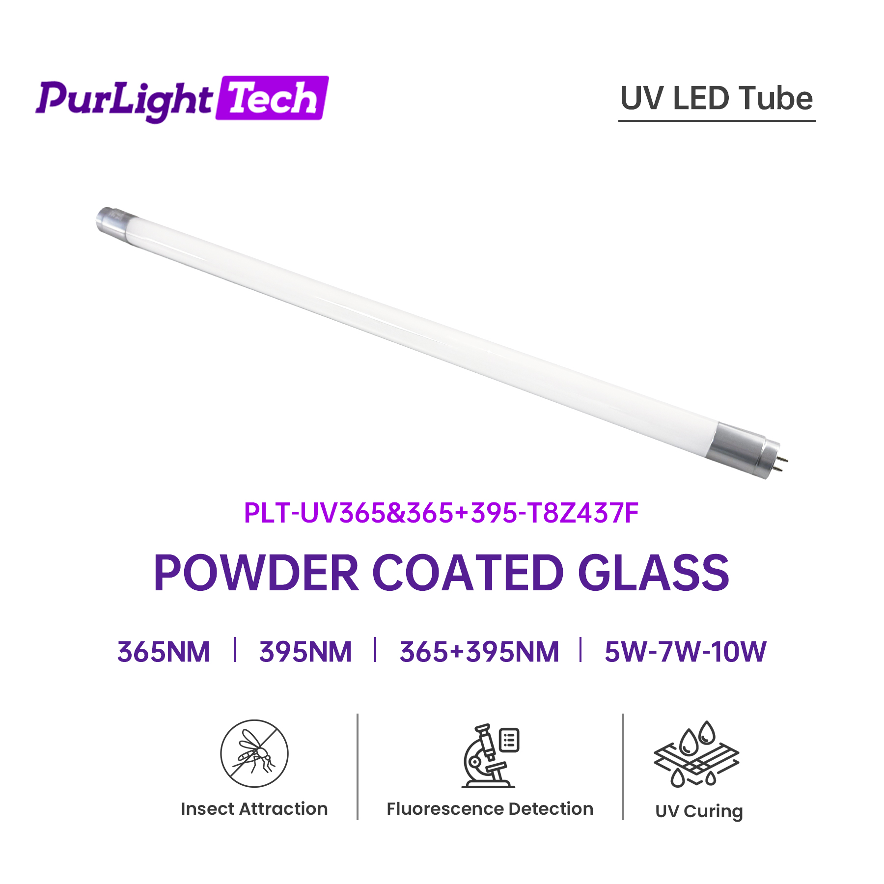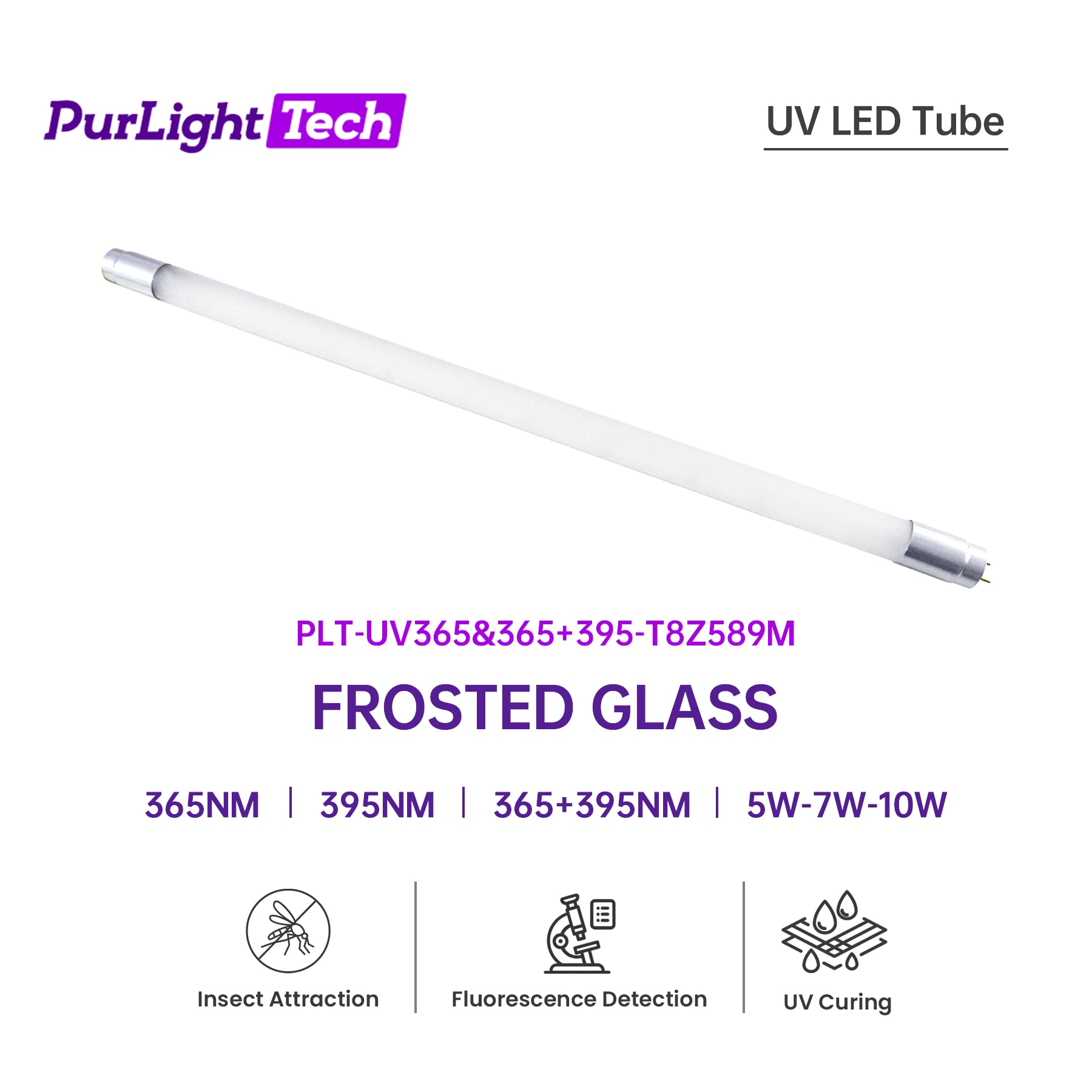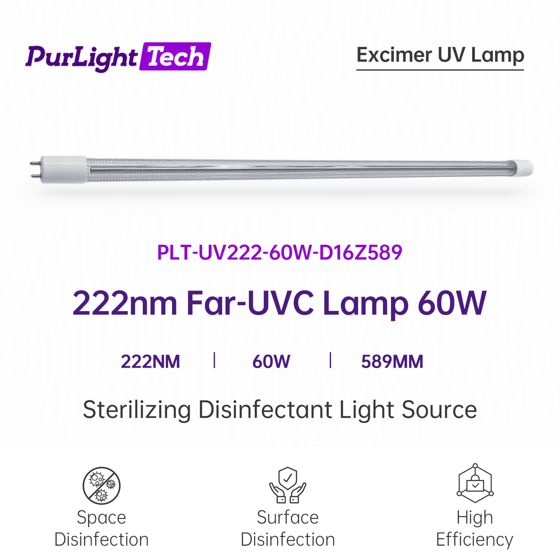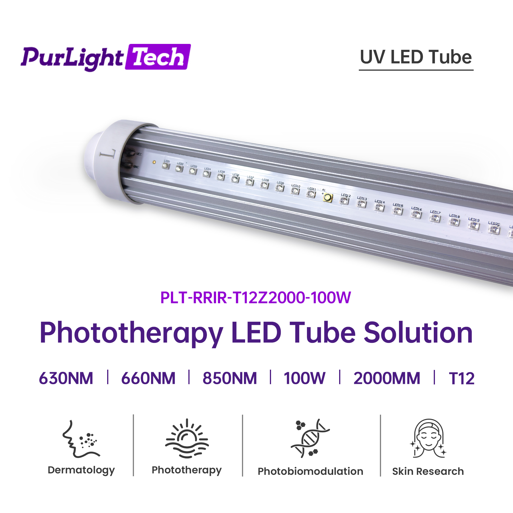
A tube datasheet describes a lamp. It does not describe a housing, an airflow, a mounting distance or a control board.
The distinction matters because the entity that carries a claim is not the lamp. Whatever a brand owner says publicly about a product — on packaging, in a listing, in an instruction sheet — attaches to the finished article, and it has to be supported by evidence about that article. A statement about a tube does not become a statement about a product. UVC LED tube for OEM products is therefore a systems question wearing a component's name.
A second reason is practical. Two products can use the same tube and behave differently, because the tube is one element of an optical and mechanical assembly. The housing decides where the light goes and how much of it arrives; the drive electronics decide whether the tube runs at the condition its data was taken under; the control logic decides when it is allowed to run at all.
A product that uses a germicidal tube to treat air or a surface will use one of two arrangements, and they are not interchangeable. UV-C disinfection product integration begins by deciding which one is being built.
A through-flow air path. Air is moved through a duct or a chamber, and the treatment happens as it passes. The requirement is about the flow: the path has to keep the air in the treated zone long enough, and it has to keep air from taking a shortcut around that zone. Duct geometry, the fan characteristic and the sealing of the enclosure are therefore part of the optical design, not separate from it. An in-duct UVC air treatment module lives or dies on whether the flow cooperates.
An irradiation chamber. Surfaces are placed in a closed chamber and treated while it is closed. The requirement here is about sightlines: the chamber must present the surfaces to the light, which usually means reflective interior surfaces and a layout that avoids self-shadowing. A drawer, a cabinet or a pass-through box built for this purpose is a lighting fixture as much as it is furniture.
What follows for a product owner is that the two arrangements cannot share one performance statement. A figure measured in a duct describes a duct. A figure measured in a chamber describes a chamber. If a product is presented as doing both, the reasonable next question is which of the two it was measured in.
|
Through-flow air path Air is moved through the treated zone as it passes. Design problem: the flow — keeping air in the zone long enough, and keeping it from bypassing the zone. |
Irradiation chamber Surfaces are placed in a closed chamber and treated while it is closed. Design problem: sightlines — presenting the surfaces to the light, and avoiding self-shadowing. |
The two arrangements are specified against different quantities, so one figure cannot describe both.
Whichever arrangement is used, three quantities sit between the tube and the result.
Distance and angle of incidence. Light from a tube arrives at a target from a direction, and how much lands depends on how far away the target is and how square it is to the light. This is why a tube placed closer is not simply "stronger": the pattern on the target changes shape, and it does not change evenly.
The minimum across the target, not the average. This is where many first designs go wrong. An average across a target surface is a convenient single number, and it is not the one that describes the result — what describes the result is the least-treated part of the target, because that part sets the outcome. A layout can look adequate on average and still leave a band near an edge, or in a shadow, well below everything else. The target surface should be mapped, and the map should be read at its minimum.
Time. The target has to remain in the light for the intended effect. In a chamber, that is the cycle time. In a duct, it is set by how long the moving air stays in the treated zone. Either way it is a product-design variable: the tube does not set it.
| Edge band of the target |
|
minimum | ||
| Centre of the target |
|
highest | ||
| Shadowed or angled area |
|
minimum |
Schematic distribution only. The minimum describes the least-treated part of the target, and that part sets the outcome; this figure carries no performance figure.
Three things are worth pinning down in writing on the tube side.
Peak wavelength, and the tolerance it is stated against. A peak wavelength figure is incomplete on its own. A tolerance only means something with two further statements: what it is measured against, and under what conditions. A tolerance quoted without them cannot be compared with another supplier's, and it cannot be used to predict behaviour in a housing whose thermal conditions differ. Ask for the reference and the test conditions, and treat UVC LED tube wavelength tolerance as a three-part statement rather than a number.
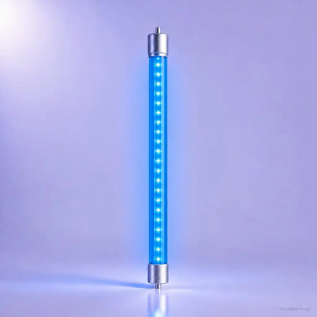
Form factor, including the end caps. A tube that has to drop into an existing fixture is a mechanical part before it is an optical one. Aluminium end caps matter for reasons that are not cosmetic: they define the mechanical interface, they are where the tube is gripped and located, and they are part of how the assembly handles heat. For a germicidal LED tube replacement, the electrical and mechanical interfaces have to be confirmed against the host fixture rather than inferred from a photograph.
Driver and socket compatibility. This is the most common source of a project that works on a bench and fails in production. The tube is designed for a drive condition; the product's driver has to deliver it. Three traps are worth checking deliberately: a driver that runs the tube at a different current than its data was taken at; a socket designed around a different lamp technology that does not present the same interface; and a control scheme that switches the tube in a way the driver was not built for. UVC tube driver compatibility is a confirmation step, not a footnote.
The remaining work is not optional, and it does not belong to the tube supplier.
A complete enclosure and interlocks. UVC radiation is hazardous to eyes and skin. A product has to keep the radiation inside while it operates, and it has to stop emitting when it is opened. UV-C product safety interlock design is part of the housing design, and it has to be reliable enough that a user cannot defeat it by accident.
Occupancy sensing. Where a product could be operated in a way that exposes a person, or where a person could enter a treated space, sensing has to be part of the design. The engineering question is what the sensor covers and what happens when it fails — not only whether one is fitted.
Warning markings and instructions. Outputs that can injure have to be labelled and explained in the language of the market where the product is sold. This is a documentation task with a deadline, not a finishing touch.
Testing and certification for the destination market. A product that emits radiation is subject to market-access requirements in the United States. The FDA regulates germicidal ultraviolet lamps and light-emitting diodes as radiation-emitting electronic products, and the manufacturer of the finished product — not the tube supplier — is the party that has to satisfy those requirements and keep the records behind them. Confirm the current requirements with the regulator and with a qualified test house before the design is frozen, because the enclosure may have to change as a result.
|
Tube side — stated characteristics of a part Peak wavelength and its tolerance, together with the reference and the conditions The physical and electrical interface The conditions any figure was taken under |
Product side — properties of the finished article Enclosure, interlocks and occupancy sensing Markings, instructions, testing and certification The measurement that establishes what the product does |
The tube side supplies parts. The product side supplies the evidence.
It is worth being explicit about the boundary, because it is where expectations go wrong.
On the tube side, a supplier can provide the stated characteristics of a part: the peak wavelength and its tolerance together with the reference and the conditions, the physical and electrical interface, and the conditions under which any figure was taken.
On the product side, only a measurement of the finished product can establish what the product does. That measurement has to be made on the built article, in its own geometry, with its own airflow or chamber, and it has to be repeatable. No document about a tube substitutes for it.
The practical version of this is a sentence worth keeping: the tube side supplies parts; the product side supplies evidence.
If a product is going to carry a claim, the evidence has to be reproducible. Three things need to be written down before the first reading.
The plane. State where the measurement is taken. A reading taken at the tube and a reading taken across the target surface are different measurements.
The quantity. State what is being measured and in what units. A single spot reading and a mapped reading are not the same kind of evidence.
The conditions. State the drive setting, the ambient conditions and the configuration that applied during the measurement. A reading without its conditions cannot be compared with the next one.
Set those three and successive readings become a record. Where a product's claim is challenged, that record is the answer — not the tube datasheet.
No. It describes the tube. A claim about a product needs evidence about that product — measurement on the finished article, in its own configuration.
Three things: the figure, what the tolerance is measured against, and the conditions it was measured under. A tolerance without those two cannot be compared with another supplier's.
No. Moving a tube closer changes the pattern on the target as well as the amount arriving, and it does so unevenly. The layout has to be checked at the least-treated part of the target, not at its average.
Driver and socket compatibility. A configuration that works on a bench can fail in production if the driver runs the tube at a different condition, the fixture presents a different interface, or the control scheme switches the tube in a way the driver was not built for.
The manufacturer of the finished product. Interlocks, occupancy sensing, markings and instructions are properties of the article that is sold, and their design belongs with the housing rather than with the tube.
No. Market-access requirements attach to the product that is placed on the market. Confirm the current requirements with the regulator and a qualified test house, and allow time for the enclosure to change as a result.
This article is a technical description. UVC radiation is hazardous to eyes and skin, and equipment using it is intended to operate only in unoccupied spaces or inside a fully closed enclosure; the finished product needs reliable interlocks and occupancy sensing, and it has to complete the testing and certification applicable in the market where it is sold. Treatment of air and surfaces is a layer that sits alongside cleaning and procedural controls rather than in place of them. Nothing here is engineering, medical or legal advice, and no standard or regulation is identified by number — confirm current requirements with the regulator and a qualified test body.
 Hot News
2026-03-31
2025-03-17
2025-03-17
2025-03-17


 EN